7 Must-Know Tips for Making a Quality PC Circuit Board
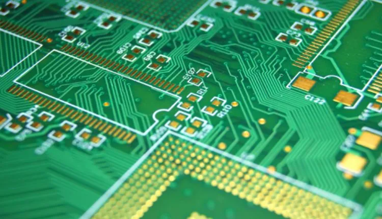
PCs are complex, and often impressive pieces of hardware. To make them run efficiently, you need circuit board technology that can keep up with boundless software innovation. With this in mind, here are seven must-know tips for making a high-quality PC circuit board:
- Consider Help from the Pros
Professional help is always recommended when it comes to building a quality, impressive PC circuit board. The amount of complexity and nuance that must go into a circuit board’s design is hard to overstate, after all. Even if you can handle certain aspects of the designing and manufacturing process, a circuit board professional can help you perfect your design, bringing it to new heights as a result.
- Be Cautious with Autorouters
The majority of printed circuit board design programs contain an autoroute feature that does the routing for you automatically. But, you shouldn’t get too enthused about this tool because auto-routing is not a perfect substitute for doing your own routing. We advise manually routing your printed circuit board whenever possible because routing is both a science and an art. This will increase accuracy and dependability. In the end, auto-routing should be taken as a guide. This process can be complex, but it’s incredibly important.
- Stay Aware of All Relevant Manufacturer Specifications
You must ascertain the requirements of your selected manufacturer before putting down the first trace. On their websites, some manufacturers list their requirements. It is advised that you get in touch with them if they don’t so that your printed circuit board will perform properly and satisfy your expectations. Before designing your printed circuit board, it is critical to be aware of your manufacturer’s requirements, including trace width, number of board layers, and trace spacing. This avoids the aggravation of having to last-minutely rewire your entire design and spending more time working on it. While tricky, having a strong understanding of the intended use of each part in your circuit board is what separates the pros from the amateurs.
- Carefully Place the Space Between Traces
Excellent traces have electrical resistance built right in. Hence, a voltage drop, power loss, and heat generation occur as current flows through them. Ultimately, you’re trying to keep the heat at bay by using proper traces spacing techniques. When modifying trace width, your expected current must be taken into consideration. You can use a trace width calculator to determine the ideal trace width for your printed circuit board. Simply enter your predicted current and trace thickness to find the appropriate trace width value. The likelihood that you will receive a board with troublesome connections decreases as your traces become wider. This consideration is key to producing quality PC circuit boards in 2023.
- Component Placement is Everything
PC Circuit boards are always complex. With this in mind, the final design’s success is determined by how components are arranged. You must comprehend each component’s features to arrange them effectively. Certain components should not be positioned next to others. Moreover, convenience requires precise component positioning. Perfecting this technique takes time, however. If you’re not confident in your ability to place components optimally, you should use a professional’s skill to ensure your PC circuit board is both functional and impressive.
- Channel Heat Using Proper Vias
On multilayer printed circuit boards, vias enable electrical communication between several layers and can dissipate heat. Just route vias beneath a component to direct heat away from it. These vias will successfully direct any extra heat away from the component. Ensure that the component’s pins are kept away from the vias. The more time and effort you put into this step, the better. Having proper via installation, and other component installation is key to keeping your circuit board design secure, and ready for professional operations.
- Ensure There’s a Ground Plane
Your traces must have a common ground to provide a single point of reference for measuring the voltage across all of them. This is particularly crucial for analog circuits. Traces can be used to route to the ground if desired. Nevertheless, if you do this, your printed circuit board can end up with a lot of distinct connections. Nonetheless, different voltage drops can result from traces with different resistance levels. Use a dedicated ground plane in your printed circuit board design to prevent a nightmare of redundant ground connections and voltage dips. A substantial layer of copper or, even better, a complete plane on a multilayer board might serve as the ground plane. All that is left to do is use vias to connect other components after the ground plane is in place. This is another particularly difficult and tricky step when it comes to designing a quality PC circuit board.


